Introduction
In the first article in this series, I provided a quick introduction to Objective-C, and talked a bit about memory management, working with the controls,
and persisting information to files. In this article, I want to introduce some of the graphics functionality. I will be using the iPad emulator as the target device for this article because of the much better display surface that it provides. But the APIs
shown here will work on the iPad, iPhone, and iPod Touch. Since these APIs were ported from Mac OS X, these APIs will work on a Macintosh as well.
Prerequisites
To take advantage of this article, you will want to have some familiarity with Objective-C and iPhone development. If you don't, then you will want to take a look at the
first article I wrote on iPhone development. You'll also want to be comfortable with math (algebra and some trigonometry) as graphics and math go hand
in hand. The only hardware you need for this article is an Intel based Macintosh running Snow Leopard and the iOS SDK.
Available APIs
The iPhone supports two graphics API families: Core Graphics/Quartz 2D and OpenGL ES. OpenGL ES is a cross platform graphics API. Quartz 2D is an Apple specific API. It is a part of the Core Graphics framework. OpenGL ES is a slimmed down version of a much
larger graphics API: OpenGL. Keep in mind that OpenGL ES is an application programming
interface; it describes the available functions, structures, semantics on how they are used, and the behaviours that the functions should have. How a device manufacturer choose to implement these behaviours and conform to this specification would be
their implementation. I point this out because I come across a lot of conversations based on a misunderstanding of the difference between interface and implementation. If that difference is hard to understand, think about this analogy: a wind up and electrical
clock both have the same visual interface and same behaviour, but their inner workings (implementation) is different. Because of the great amount of liberty with which a manufacturer may implement OpenGL ES, you'll find a wide range of performance variance
across different systems. Thankfully, on iOS devices, the lower end of the performance scale is still fairly high when compared to some other OpenGL ES capable devices out there.
Representing Colors
There are several different ways to represent a color digitally. The typical way is to express a single color by expressing the intensities of the primary colors that when mixed together will result in the same color. The primary colors are red, green, and
blue. If you were thinking of yellow as being a primary color and not green, then you are probably thinking of the primary subtractive colors (relevant when using paint on paper, but not when illuminating pixels). There are other systems of digitally representing
colors supported by Quartz 2D, but I won't discuss them here. I'll only use colors expressed in red, green, and blue. This is also called the RGB color space. Each one of the components of these colors is expressed as a floating point number. The lowest intensity
is 0, and the highest intensity is 1.0.
In addition to those pixel intensities, there's a fourth color component usually named "Alpha". The alpha component is used to represent a level of transparency. If a color is completely opaque (non-transparent), this value will be 1.0. If a color is completely
transparent (and thus invisible), the value will be 0. When an RGB color also has an alpha component depending on the system being looked at, this will either be called ARGB color space or RGBA color space (the difference being where the alpha component is
located). Within the rest of this material, RGBA will be used to describe colors of this type. While Quartz 2D supports a number of different color formats, OpenGL ES only supports RGBA.
Screen Coordinates
When positioning items on the screen, you'll often use points (CGPoint) to position items on the screen. It is a natural to assume that a point coordinate and a pixel coordinate are the same.
But in iOS, this isn't always the case. A point doesn't necessarily map to a pixel of the same coordinate. The mapping is handled by the system. You get to see it come into play the most when you are looking at how one application runs on devices with different
pixel resolutions. If you want to see the relationship between the pixels and points, you can look at the scale factor that is exposed by the
UIImage, UIScreen, or
UIView classes.
A Look at Quartz 2D and Core Graphics
With Quartz 2D, you are rendering to either a view or an in-memory image. The surface on which you draw has a color, and if you call various functions to render onto a surface if you are drawing with transparent colors, then the color will mix with whatever
is under it as it is drawn. In the example programs, we'll start off with drawing to
UIView so that you can immediately jump into seeing how Quartz 2D works. To do this, we will create a new view class derived from
UIView and will make calls to draw with Quartz 2D in the object's
(void)drawRect:(CGRect)rect method.
The Core Graphics APIs all act within a context. You'll need to get the context for your view and pass it to the Quartz 2D functions to render. If you were rendering to an in memory image, then you would pass its context instead. The context of your view
can be acquired with the following function call:
CGContextRef context = UIGraphicsGetCurrentContext();
Building Your First Quartz 2D Application
Open Xcode and create a new iOS View based application named MyDrawingApp. Once the application is created, click on the
Classes folder. We are going to create a new UIView control and perform our rendering within that view. Create a new Cocoa Touch class file by right-clicking on the
Classes folder and selecting "Add New File". Select Objective-C class and choose
UIView as the
Subclass of setting. (The default is NSObject. Make sure this isn't selected.) Click on "Next", and when you are prompted for a name for the file, enter "MyDrawingView.m". Both a
*.h and a *.m file will be created.
For this first program, the only thing I want to do is get something drawing on the screen; other than drawing something on the screen, there's nothing more that this program will do. Open the
*.m file for the class that you just added. We'll start off with overriding the classes initialization method. Our instances of this class are going to be created within the Interface Builder. Objects created that way are initialized with a call to
initWithCoder: instead of a call to
init. So that's the method we need to override.
-(id) initWithCoder:(NSCoder*)sourceCoder
{
    if( ( self = [super initWithCoder:sourceCoder]))
    {
        //place any other initialization  here
    }
    return self;
}
Right now, there's nothing that we need to do in the initialization method. But I've had you include it here as a place holder for other code. To display this view on the phone, we are going to set it as the base class for the applications. Within Xcode,
find MyDrawingAppViewController.xib and open it in the Interface Builder. Press command-4 to ensure that the identity inspector is open. You'll see that currently the view is set to inherit from
UIView. We want to instead have it inherit from our class
MyDrawingView. Save your changes and close the Interface Builder. Compile and run your code to make sure that all is in order. Once you've done this, we are ready to start drawing!
In MyDrawingView.m, there is a method named drawRect: that contains no code. That's where we are going to place our drawing code. We'll need to get our graphics context, set our drawing
color and other properties, and then draw our shapes on the screen. For now, let's draw a simple line.
// Only override drawRect: if you perform custom drawing.
// An empty implementation adversely affects performance during animation.
- (void)drawRect:(CGRect)rect {
    UIColor* currentColor = [UIColor redColor];
    CGContextRef    context = UIGraphicsGetCurrentContext();

    //Set the width of the "pen" that will be used for drawing
    CGContextSetLineWidth(context,4);
    //Set the color of the pen to be used
    CGContextSetStrokeColorWithColor(context, currentColor.CGColor);

    //Move the pen to the upper left hand corner
    CGContextMoveToPoint(context, 0, 0);
    //and draw a line to position 100,100 (down and to the right)
    CGContextAddLineToPoint(context, 100, 100);
    //Apply our stroke settings to the line.
    CGContextStrokePath(context);

    [currentColor release];
}
Open MyDrawingAppViewController.xib and single-click on the "View" icon. While it is
highlighted, press command-4 to ensure that the Identity Inspector is selected. Next to the setting for Class, change the drop-down from
UIView to MyDrawingView. Close Interface Builder and save your changes. Return to Xcode and run your project. You'll see a red line
on the screen from the upper left corner.
While not directly related to graphics, I want to venture into a bit on touch interactions. This program would probably be more interesting if it were interactive. We are going to change it so that the line will be drawn between two points that you select
by dragging your finger on the screen. We are also going to change the program to persist its reference to the color instead of grabbing a new one every time the screen is refreshed. Open the
MyDrawingViewView.h file and make the following additions:
#import <uikit/uikit.h>

@interface MyDrawingView : UIView {
    CGPoint fromPoint;
    CGPoint toPoint;
    UIColor* currentColor;
}

@property CGPoint fromPoint;
@property CGPoint toPoint;
@property UIColor* currentColor;

@end
The appropriate @synthasize statements will need to be added to the top of the
MyDrawingView.m file. Add the following to that file:
#import "MyDrawingView.h"

@implementation MyDrawingView

@synthesize fromPoint;
@synthesize toPoint;
@synthesize currentColor;
I've not said anything about touch interactions up to this point. I'll talk about touch events and other event handling in another article; for now, I'm going to take the
satisfying route and speed through the interactions of interest. There are three events that we will need to respond to to add touch interactions to the program.
touchesBegan:,
touchesEnded:
touchesMoved:
MyDrawingView.m file.
- (void) touchesBegan:(NSSet*)touches withEvent:(UIEvent*)event
{
    UITouch* touchPoint = [touches anyObject];
    fromPoint = [touchPoint locationInView:self];
    toPoint = [touchPoint locationInView:self];

    [self setNeedsDisplay];
}

-(void)touchesEnded:(NSSet *)touches withEvent:(UIEvent *)event
{
    UITouch* touch = [touches anyObject];
    toPoint=[touch locationInView:self];
    [self setNeedsDisplay];
}

-(void)touchesMoved:(NSSet *)touches withEvent:(UIEvent *)event
{
    UITouch* touch = [touches anyObject];
    toPoint = [touch locationInView:self];
    [self setNeedsDisplay];
}
The only things left are to change our drawing code so that instead of drawing between two fixed points, it will draw between the points that we touched, and remove the declaration and release of
currentColor within our drawing code (since we are now using a member property to store the color).
- (void)drawRect:(CGRect)rect {
    CGContextRef    context = UIGraphicsGetCurrentContext();

    CGContextSetLineWidth(context,4);
    CGContextSetStrokeColorWithColor(context, currentColor.CGColor);


    CGContextMoveToPoint(context,fromPoint.x , fromPoint.y);
    CGContextAddLineToPoint(context, toPoint.x, toPoint.y);
    CGContextStrokePath(context);
}
Run the program and try dragging your finger (or mouse) on the screen in various points. You'll see the line draw between points that you touch.
Working with Images
There are two images available on the iPhone. These are CGImage and
UIImage. CGImage is a struct that contains image data that can be passed around to various Core Graphics functions.
UIImage is an Objective-C class. By far, the
UIImage class is much easier to use, so let's start with using it to draw an image in our program. Find an image on your computer that's under 500x500 pixels. The image can be a PNG or JPEG file.
Within your project in Xcode, you will see a folder called Resources. Click-and-drag your image to the
Resources folder in Xcode, and when prompted, select the option to Copy items into destination group's folder (if needed). I'm using a file named
office.jpg, and will refer to my image file by this name. Remember to replace this with the name of your image.
Within the MyDrawingView.h file, declare a new UIImage* variable named
backgroundImage. In the
MyDrawingView.m implementation file, add a @syntasize backgrounImage; statement. We need to load the image from the resources when the view is initialized. Within the
-(id)initWithCoder: method, add
backgroundImage = [UIImage imageNamed:@"office.jpg"];. Remember to replace
@"office.jpg" with the name of your image file. This line will load the image from the resources. Within the top of the
-(void)drawRect: method, add the following two lines:
CGPoint drawingTargetPoint = CGPointMake(0,0);
[backgroundImage drawAtPoint:drawingTargetPoint];
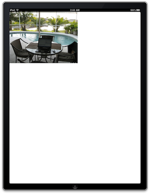
If you run the program now, it will have a background image rendered behind the lines that you draw.
Points vs. Pixels
There's a conceptual layer of separation between the physical resolution of the screen of an iOS device and the coordinates that you use for drawing. In many graphical environments, the terms point and pixel could be used interchangeably. On iOS devices,
the Operating System will map points to pixels. Drawing something at position (10,25) may or may not cause an object to appear at 10 pixels from the left and 25 pixels from the top. The relationship between points and the actual pixels can be queried though
a scale factor that can be read from UIScreen,
UIView, or
UIImage
to take advantage of the higher resolution of the iPhone 4's screen, when the code draws a line or an image on the device's screen, it will take up the same amount of proportional space on the device's screen.
Vector based operations such as drawing rectangles, lines, and other geometric shapes will work on standard and higher resolution devices just fine without any need to adjust the code. For bitmaps, there's a bit of additional work that you'll need to do.
You will need to have a standard and high resolution version of your image to get the best possible results. The name for your resources should conform to a specific pattern. There's a pattern for
standard resolution devices and another for high resolution devices.
| Standard resolution: | <ImageName>[DeviceModifier].<fileExtention> |
| High resolution: | <ImageName>@2[DeviceModifier].<fileExtention> |
The [DeviceModifier] part of the resource name is optional. It can be the string
~iphone or
~ipad@2' in the name. The width and
height of the high resolution image should be twice the width and height of the standard resolution image. (To any one familiar with MIP maps, this will be familiar.)
Paths
A path describes a shape. Paths can be made of lines, rectangle, ellipses, and other shapes. Coordinates within a drawing space are specified using points. It's easy to think of points as pixels, but they are not the same thing (more on that in the
Points vs. Pixels section). In general, you'll be communicating points by passing a pair of floating point numbers or using a
CGPoint structure. You've already gotten to see
CGContextAddLineToPoint in the program built above. There also exists a
CGContextAddLines function for drawing multiple lines whose points are passed in an array.
CGContextAddEllipseInRect adds ellipses. Both of these functions accepts a
CGRect that defines the rectangle that bounds the shape to be drawn.
Curved lines (more specifically, Bezier curves) can be generated with the function
CGContextAddCurveToPoint. The curved line will start at the point that the last drawing operation occurred (remember that you can change this point using
CGMovePointToDraw), and will end at the point specified in the function call, and its curve will be affected by two control points that are also passed in the function call. If you've never worked
with Bezier curves before, there's a good article on them at
Wikipedia.org.
If you need to create a complex path (a path composed of many paths), you'd start off by calling
CGContextBeginPath, and then set the starting point of your path with a call to
CGContextMoveToPoint. Then make calls to add shapes to the path. When you are done, close the path with
CGContextClosePath. Creating a path doesn't render it to the screen. It's not rendered until you
paint it. Once it has been painted, the path is removed from the graphics context and you can begin rendering a new path (or some other operation).
To paint a path, you apply a stroke and/or fill to it with CGContextStrokePath or
CGContextFillPath. The stroke affects how the lines that surround a path appear (a.k.a. border). Among other functions, use the functions
CGContextSetLineWidth and
CGContextSetStrokeColor or
CGContextSetStrokeColorWithColor to set the color of the lines. Calling
CGStrokePath will apply the stroke to the current path.
The filling rules for simple geometries is straightforward, and doesn't need much explanation; the area inside the lines is filled. When creating your own custom paths with borders that overlap, the rules for the area that gets filled are a little more complex.
According to the Apple documentation, the rule used is called the nonzero winding number rule (found
here). The procedure described for deciding whether a certain point is within the area to be filled or not is a little abstract. Choose the point you want to test, and draw a line from it to beyond the borders of the drawing,
counting the number of path segments that it intersects. Starting with a count of zero, add to your count every time the line intersects a path segment going from left to right, and subtract every time it crosses a path segment going from right to left. If
the result is odd, then the point should be filled. If the result is even, then the point should not be filled. An alternative rule is to simply count the number of times the line drawn in the above procedure crosses a path segment irrespective of the direction
of the segment. If the result is even, then don't fill the point. Otherwise the point is to be filled. This is called the
even-odd rule.
Clipping
A context automatically has a clipping surface that is the same size as the surface on which it is drawing. You can create an additional surface area if you need to further restrict the area in which drawing occurs. To create a new clipping area, you create
a path and then call a clipping function instead of a drawing function. The resulting clipping area is the intersection of the present clipping area and the one being applied. Clipping is considered part of the graphics state. If you need to set and restore
the clipping area, you'll need to save and then restore the context.
CGContextClip will apply the current path against the current clipping area.
CGContextClipToRect will apply a rectangle to the clipping area.
CGContectClipToRects will apply multiply rectangles to the clipping area.
Gradients
A gradient is an area that gradually changes color. Quartz 2D offers two types of gradients: a linear (or axial) gradient and a radial gradient. The changes in your gradient colors can also include changes in the alpha value. There are two objects available
for creating gradients: CGShadingRef and
CGGradient.
The CGGradient type is the easier of the two methods to use for creating a gradient. It takes a list of locations and colors, and from that list, the color for each point in the gradient is
calculated for you. I only use RGB color space in my code examples so that's what I will be using for the color space option for the gradients. Some of Apple's documentation will refer you to
CGColorSpaceCreateWithName(kCGColorSpaceGenericRGB); to do this, but ignore that. That function is deprecated. Instead, use
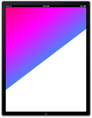
CGColorSpaceCreateDeviceRGB();. If you add the following code to the beginning of the
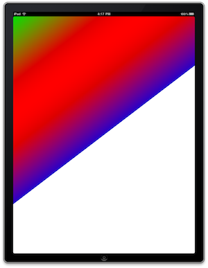
-(void)drawRect function and rerun the program, you'll see a linear gradient rendered in the background.
//Gradient related variables
CGGradientRef myGradient;
CGColorSpaceRef myColorSpace;
size_t locationCount = 3;
CGFloat locationList[] = {0.0, 0.5, 1.0};
CGFloat colorList[] = {
    1.0, 0.0, 0.5, 1.0, //red, green, blue, alpha
    1.0, 0.0, 1.0, 1.0,
    0.3, 0.5, 1.0, 1.0
};
myColorSpace = CGColorSpaceCreateDeviceRGB();
// CGColorSpaceCreateWithName(kCGColorSpaceGenericRGB);
myGradient = CGGradientCreateWithColorComponents(myColorSpace, colorList,
             locationList, locationCount);

//Paint a linear gradient
CGPoint startPoint, endPoint;
startPoint.x = 0;
startPoint.y = 0;
endPoint.x = CGRectGetMaxX(self.bounds)/2;
endPoint.y = CGRectGetMaxY(self.bounds)/2;

CGContextDrawLinearGradient(context, myGradient, startPoint, endPoint,0);
If you wanted to do a radial gradient instead of a linear gradient, then instead of calling
CGContextDrawLinearGradient, you would need to call
CGContextDrawRadialGradient().
//Radia Gradient Rendering
float startRadius = 20;
float endRadius = 210;
CGContextDrawRadialGradient(context, myGradient, startRadius,
                            startPoint, endRadius, endPoint, 0);
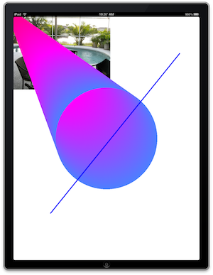
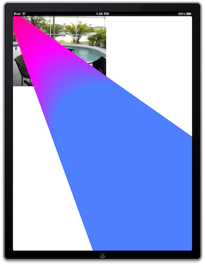
The second circle of this radial gradient is centered with the center of the screen. So the gradient stops with the circle. Optionally, the gradient could be set to continue beyond the circle or extend before the beginning of the first circle. To do this,
the last parameter should contain the option kCGGradientDrawsAfterEndLocation to extend the gradient past the end point, or the option
kCGGradientDrawsBeforeStartLocation to have the gradient stretched to the area before the start point. The result of using this option with the linear and radial gradients can be seen below.
|
|
|
CGContextDrawRadialGradient(context, myGradient, startPoint, startRadius, endPoint, endRadius, kCGGradientDrawsAfterEndLocation); |
CGContextDrawLinearGradient(context, myGradient, startPoint, endPoint, kCGGradientDrawsAfterEndLocation); |

Using CGShadingRef
CGShadingRef takes a
CGFunction that you create which contains a function that is used for calculating the colors in a gradient. The
CGShading object also contains information on what type of gradient is being generated (linear or radial), and the starting and ending points for the gradient. Once the
CGShading object is created and populated, the gradient is rendered with a call to the function
CGContextDrawShading.
When you create your shading function, there are three parameters that you'll need to define. The function's return type is
void.
void *info- Pointer to the data that you decide to pass to your function.const float *inValue- The input values for your function. You define the input range for this parameter.float* outValues- An array to the output values for your function. You must have one output value for each component of your color space, plus the alpha component. The range for each component
is between 0 and 1.
Your function will be called several times, with values ranging from the low end to the high end of the defined input range over the length of the gradient. For my example, I'm going to apply a
sin function to the input value.
static void myCGFunction ( void * info, const float *in, float * outValue)
{
    int componentCount = (int)info;
    float phaseDelta = 2*3.1415963/(componentCount-1);
    outValue[componentCount-1] = 1;            //Set the alpha value to 1
    for(int n=0;n<componentCount-1;++n)
    {
        outValue[n] = sin(phaseDelta*n+3.0*(*in));
    }
}
Once this function is defined, you'll need to package it into a CGFunctionref structure. You can use the
CGFunctionCreate function to do this. In the following code, I initialize some variables to use as the parameters for
CGFunctionCreate and pass a pointer to my function. The end result is stored in
myFunctionRef.
static const float inputRange[] = {0,1};
static const float outputRange[] = {0,1,  0,1,  0,1,  0,1  };
static const  CGFunctionCallbacks callback = { 0, &myCGFunction, NULL};

// The total number of components needed is going to be one greater than
// the number of components in the selected color space.
int colorComponentCount = 1 + CGColorSpaceGetNumberOfComponents(myColorspace);

CGFunctionRef myFunctionRef =
  //I'm passing the number of components as the option value
  CGFunctionCreate((void*)colorComponentCount,
  1,//The callback function takes one value for its input
  inputRange, //The range of the values for
  colorComponentCount,
  outputRange,
  &callback
);
With the CGFunctionRef object, you create the appropriate
CGSharingRef struct using either
CGShadingCreateAxial or
CGShadingCreateRadial. You then render your gradient using
CGContextDrawShading.
CGShadingRef myShading = CGShadingCreateAxial(myColorSpace,
             startPoint, endPoint, myFunctionRef, false, false);
CGContextDrawShading(context, myShading);
Patterns
A pattern is a set of graphics operations that are repeated over and over again over a surface. Quartz 2D will divide an area into subsections of cells, and will use a callback function defined in your program to render each cell. The cells will be of uniform
size, and there may be some spacing between each row and each column in the cell (it's up to you how much spacing is present). There are two types of patterns: color patterns and stencil patterns. Stencil patterns are like masks; they don't have a color in
and of themselves, but can be applied against a color. Think of them as being like a rubber stamp; you could apply ink of any color against a stamp and the stamp itself doesn't have an inherent color. Once you have a pattern defined, it is used in much the
same way that you would use s solid color.
To start off, you'll need to define a function that renders your pattern. Much like the Shading function (discussed in the
gradient section), the first parameter will be data that you defined. The next parameter is the context on which your pattern is to render. The function's prototype is defined as follows:
typedef void (*CGPatternDrawPatternCallback) (
                void *info,
                CGContextRef context
            );
When using a pattern, the color space must be set. This is done through the
CGContextSetFillColorSpace
CGColorSpaceRef object. You can create this using
CGContextSetFillColorSpace, passing
NULL as its only parameter. After the colorspace has been set, it can be released with a call to
CGColorSpaceRelease.
void SetPatternColorSpace(CGContextRef context)
{
    CGColorSpaceRef myColorSpace = CGContextSetFillColorSpace(NULL);
    CGContextSetFillColorSpace(context, myColorSpace);
    CGColorSpaceRelease(myColorSpace);
}
The function for creating a pattern takes a lot of parameters. Let's take a look at the function's prototype and then work through what each one of the parameters means:
CGPatternRef CGPatternCreate (  void *info,
                                CGRect bounds,
                                CGAffineTransform matrix,
                                float xStep,
                                float yStep,
                                CGPatternTiling tiling,
                                int isColored,
                                const CGPatternCallbacks *callbacks );
As per usual, the info parameter contains data that you want to pass to your callback. The
bounds parameter contains the size of one cell within your pattern. The
matrix parameter contains a transformation matrix to be applied to the pattern. This could be used for operations such as scaling or rotating the pattern. The
xStep and yStep parameters contain the amount of horizontal and vertical spacing to put between the pattern cells. The tiling parameter
can have one of three values.
kCGPatternTilingNoDistortion- pattern is not distorted when rendered, and spacing may be varied as much as one device pixel.kCGPatternTilingConstantSpacingMinimalDistortion- pattern may be distorted by as much as one device pixel.kCGPatternTilingConstantSpacing- the pattern may be distorted to improve efficiency.
isColored is set to
true if the pattern is a color pattern, and
false if it is a stencil pattern. The last parameter is a
CGPatternCallbacks structure. This struct is defined as follows:
struct CGPatternCallbacks
{
    unsigned int version;
    CGPatternDrawPatternCallback drawPattern;
    CGPatternReleaseInfoCallback releaseInfo;
};
The version field should be set to 0.
drawPattern is a pointer to your rendering function. If you had any cleanup that needed to be done (releasing memory) after your pattern is done rendering, a pointer to your cleanup function would
go in releaseInfo. Otherwise, this parameter should be
NULL. For my example, I'm creating a simple pattern that is composed of a circle within a square. I'm passing the size of the pattern in the
info parameter.
svoid MyPatternFunction(void* info, CGContextRef context)
{
    CGRect* patternBoundaries = (CGRect*)info;
    float myFillColor[] = {1,0,0,1}; //red;

    CGContextSaveGState(context);

    CGContextSetRGBFillColor(context, 0,1,1,1);
    CGContextFillRect(context, *patternBoundaries);
    CGContextSetFillColor(context, myFillColor);
    CGContextFillEllipseInRect(context, *patternBoundaries);

    CGContextFillPath(context);
    CGContextRestoreGState(context);
}
In bringing all of this to a working example. I've created a function called
PaintMyPattern(CGContextRef, CGRect)
function and the functions on which it depends follow:
//Forward declaration for top of implementation file. May not be necessary

//depending on where in your file that you past these functions

void MyPatternFunction(void* info, CGContextRef context);

void PaintMyPattern(CGContextRef context, CGRect targetRect);

void SetPatternColorSpace(CGContextRef context);
//The function definitions

void PaintMyPattern(CGContextRef context, CGRect targetRect)

{

    CGPatternCallbacks callbacks = { 0, &MyPatternFunction, NULL };

    CGContextSaveGState(context);

    CGPatternRef myPattern;

    SetPatternColorSpace(context);
    CGRect patternRect = CGRectMake(0,0,32,32);

    myPattern = CGPatternCreate((void*)&patternRect,

                                targetRect,

                                CGAffineTransformMake(1, 0, 0, 1, 0, 0),

                                32,

                                32,

                                kCGPatternTilingConstantSpacing,

                                true,

                                &callbacks

                                );

    float alpha = 1;

    CGContextSetFillPattern(context, myPattern, &alpha);

    CGPatternRelease(myPattern);

    CGContextFillRect(context, targetRect);
    CGContextRestoreGState(context);

}
void SetPatternColorSpace(CGContextRef context)

{

    CGColorSpaceRef myColorSpace = CGColorSpaceCreatePattern(NULL);

    CGContextSetFillColorSpace(context, myColorSpace);

    CGColorSpaceRelease(myColorSpace);

}
void MyPatternFunction(void* info, CGContextRef context)

{

    CGRect* patternBoundaries = (CGRect*)info;

    float myFillColor[] = {1,0,0,1}; //red;


    CGContextSaveGState(context);
    CGContextSetRGBFillColor(context, 0,