
Summary(总结)
In the previous tutorial, we setup a vertex buffer and passed one triangle to the GPU. Now, we will actually step through the graphics pipeline and look at how each stage works. The concept of shaders and the effect system will be explained.
Note that this tutorial shares the same source code as the previous one, but will emphasize a different section.
在先前的教程中, 我们建立了顶点缓存并把一个三角形传给GPU.现在我们将会真正的建立图形管道和看看各阶段的如果工作.着色器和效果系统的观念将会被解释.
注意该教程中着色器的代码和先前的代码是一样的.但是会强调不同的部分
Source(源程序)
(SDK root)\Samples\C++\Direct3D10\Tutorials\Tutorial03
Navigation(导航)
The Graphics Pipeline(图形管道)
In the previous tutorial, we setup the vertex buffer, and then we associated a vertex layout with a technique object. Now, we will explain the technique object and the shaders that compose it. To fully understand the individual shaders, we will take a step
back and look at the whole graphical pipeline.
In Tutorial 2, when we called Apply from the technique, we actually bound our shader to a stage in the pipeline. Then, when we called Draw, we start processing the vertex data passed into the graphics pipeline. The following sections describe in detail what
happens after the Draw command.
在前面的教程中,我们建立了顶点缓存,然后我们用technique对象关联顶点布局.现在我们将解释technique对象和着色器,为了更好的理解着色器,我们回到整个图形管道.
在教程2中, 当我们从technique中调用应用时, 我们其实限制我们的着色器在管道中.然后我们调用绘制函数,我们开始通过图形管道处理顶点数据.接下来的部分描述绘制命令后的细节.
Shaders(着色器)
In Direct3D 10, shaders reside in different stages of the graphics pipeline. They are short programs that, executed by the GPU, take certain input data, process that data, and then output the result to the next stage of the pipeline. Direct3D 10 supports
3 types of shaders: vertex shader, geometry shader, and pixel shader. A vertex shader takes a vertex as input. It is run once for every vertex passed to the GPU via vertex buffers. A geometry shader takes a primitive as input, and is run once for every primitive
passed to the GPU. A primitive is a point, a line, or a triangle. A pixel shader takes a pixel (or sometimes called a fragment) as input, and is run once for each pixel of a primitive that we wish to render. Together, vertex, geometry, and pixel shaders are
where the meat of the action occurs. When rendering with Direct3D 10, the GPU must have a valid vertex shader and pixel shader. Geometry shader is an advanced feature in Direct3D 10 and is optional, so we will not discuss geometry shaders in this tutorial.
在Directx3D 10 中,着色器处于图形管道的不同阶段.他们是短小的程序,被GPU解释,带进某些输入数据, 处理这些数据,并且输出结果到下一阶段的管道,Directx3D 10 支持3种着色器:顶点着色器,几何着色器,像素着色器.顶点着色器把顶点作为输入,它为每个经过GPU顶点缓存中的顶点执行一次, 几何着色器把元件作为输入,他为每个经过GPU的元件执行一次.一个元件是一个点,一条线,或者是一个三角形,像素着色器把像素(有时叫做片段)作为输入,他为每个经过GPU的像素执行一次.当渲染Direct3D
10时,GPU必须有一个有效的顶点着色器和像素着色器.在Direct3D中几何着色器是高级特性并且是可选的,所以在这章中我们不讨论几何着色器.
Vertex Shaders(顶点着色器)
Vertex shaders are short programs that are executed by the GPU on vertices. Think of vertex shaders as C the active vertex shader once for each vertex, passing the vertex's datafunctions that take each vertex as input, process the input, and then output
the modified vertex. After the application passes vertex data to the GPU in the form of a vertex buffer, the GPU iterates through the vertices in the vertex buffer, and executes to the vertex shader as input parameters.
While a vertex shader can be used to carry out many tasks, the most important job of a vertex shader is transformation. Transformation is the process of converting vectors from one coordinate system to another. For example, a triangle in a 3D scene may have
its vertices at the positions (0, 0, 0) (1, 0, 0) (0, 1, 0). When the triangle is drawn on a 2D texture buffer, the GPU has to know the 2D coordinates of the points on the buffer that the vertices should be drawn at. It is transformation that helps us accomplish
this. Transformation will be discussed in detail in the next tutorial. For this tutorial, we will be using a simple vertex shader that does nothing except passing the input data through as output.
In the Direct3D 10 tutorials, we will write our shaders in High-Level Shading Language (HLSL), and the applications will use these shaders with the effect system. Recall that our vertex data has a 3D position element, and the vertex shader will do no processing
on the input at all. The resulting vertex shader looks like the following:
顶点着色器是短小的程序,被GPU解释.把顶点着色器想成C,通过顶点的函数把每个顶点当成输入,处理输入,然后输出修改后的顶点.在应用程序从顶点缓存中传递顶点数据给GPU后,GPU重复通过把顶点缓存中的顶点当作顶点着色器的输入参数.
一个顶点着色器能被执行很多任务,最重要的工作是转换.就是顶点在坐标系统中转变为另一个的过程,一个三角形在3D场景中可能在(0, 0, 0) (1, 0, 0) (0, 1, 0)上有顶点.当三角形被绘制在2D纹理缓存中时,GPU必须知道该点所画的2D坐标.这样才能帮助我们完成转变,转换将会在下章详细讨论.这章中,我们使用简单的顶点着色器,该着色器除了输出输入的数据外不做任何事.
在Direct3D 10 教程中, 我们将会写我们自己的着色器使用高级着色器语言(HLSL),然后这些应用程序将会使用这些带着效果系统的着色器.回忆我们顶点数据包含了3D元素,并且顶点着色器不会处理输入.最后的顶点着色器像下面这样.
    float4 VS( float4 Pos : POSITION ) : SV_POSITION
    {
        return Pos;
    }
This vertex shader looks a lot like a C function. HLSL uses C-like syntax to make learning easier for C/C++ programmers. We can see that this vertex shader, named VS, takes a parameter of float4 type and returns a float4 value. In HLSL, a float4 is a 4-component
vector where each component is a floating-point number. The colons define the semantics of the parameter as well as the return value. As mentioned above, the semantics in HLSL describe the nature of the data. In our shader above, we choose POSITION as the
semantics of the Pos input parameter because this parameter will contain the vertex position. The return value's semantics, SV_POSITION, is a pre-defined semantics with special meaning. This semantics tells the graphics pipeline that the data associated with
the semantics defines the clip-space position. This position is needed by the GPU in order to drawn pixels on the screen. (We will discuss clip-space in the next tutorial.) In our shader, we take the input position data and output the exact same data back
to the pipeline.
这个着色器像C函数一样,HLSL使用C风格的语法来更容易的学习C/C++程序.我们看到这个顶点着色器,名为VS,使用float4类型的参数,返回float4类型的值.在HLSL中,一个float4是一个4部分组成的顶点,每一部分是一个float顶点数..............
Pixel Shaders(像素着色器)
Modern computer monitors are commonly raster display, which means the screen is actually a two-dimensional grid of small dots called pixels. Each pixel contains a color independent of other pixels. When we render a triangle on the screen, we don't really
render a triangle as one entity. Rather, we light up the group of pixels that are covered by the triangle's area. Figure 2 shows an illustration of this.
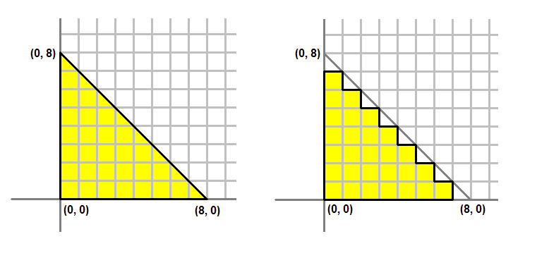 Figure 2. Left: What we would like to draw. Right: What is actually on the screen.
The process of converting a triangle defined by three vertices to a bunch of pixels covered by the triangle is called rasterization. The GPU first determines what pixels are covered by the triangle being rendered. Then it invokes the active pixel shader
for each of these pixels. A pixel shader's primary purpose is to compute the color that each pixel should have. The shader takes certain input about the pixel being colored, computes the pixel's color, then outputs that color back to the pipeline. The input
that it takes comes from the active geometry shader, or, if a geometry shader is not present, such as the case in this tutorial, the input comes directly from the vertex shader.(像素着色器的输入来自顶点着色器)
The vertex shader we created above outputs a float4 with the semantics SV_POSITION. This will be the input of our pixel shader. Since pixel shaders output color values, the output of our pixel shader will be a float4. We give the output the semantics SV_TARGET
to signify outputting to the render target format. The pixel shader looks like the following:
    float4 PS( float4 Pos : SV_POSITION ) : SV_Target
    {
        return float4( 1.0f, 1.0f, 0.0f, 1.0f );    // Yellow, with Alpha = 1
    }
Effect System()
Our effect file consists of the two shaders, vertex shader and pixel shader, and the technique definition. The technique definition will set the corresponding shaders to each section. In addition, there is also the semantic to compile the shader. Note that
the geometry shader is left NULL because it's not required and will be covered later.
    // Technique Definition
    technique10 Render
    {
        pass P0
        {
            SetVertexShader( CompileShader( vs_4_0, VS() ) );
            SetGeometryShader( NULL );
            SetPixelShader( CompileShader( ps_4_0, PS() ) );
        }
    }
Creating the Effect and Effect Technique
In the application code, we will need to create an effect object. This effect object represents our effect file, and is created by calling D3D10CreateEffectFromFile(). Once we have created the effect object, we can call the ID3D10Effect::GetTechniqueByName()
method, passing in "Render" as the name, to obtain the technique object that we will be using to do the actual rendering. The code is demonstrated below:
    // Create the effect
    if( FAILED( D3DX10CreateEffectFromFile( L"Tutorial03.fx", NULL, NULL, D3D10_SHADER_ENABLE_STRICTNESS, 0, g_pd3dDevice, NULL, NULL, &g_pEffect, NULL ) ) )
        return FALSE;

    // Obtain the technique
    g_pTechnique = g_pEffect->GetTechniqueByName( "Render" );
Putting It Together
After walking through the graphics pipeline, we can start to understand the process of rendering the triangle we created at the beginning of Tutorial 2. Creating Direct3D applications requires two distinct steps. The first would be creating the source data
in vertex data, as we've done in Tutorial 2; the second stage would be to create the shaders which would transform that data for rendering, which we showed in this Tutorial.