原文地址:http://blog.csdn.net/kellycan/article/details/6394737
1 Linux I2C驱动架构
Linux下I2C驱动的架构图如下:
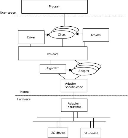
图1.1 Linux下I2C驱动架构
如上图所示,每条I2C总线会对应一个adapter,而每条I2C总线上则可以有多个 client,在linux kernel中,通过I2C core层将I2C client与I2C adapter关联起来,Linux 中I2C驱动代码位于drivers/i2c目录。
Linux中I2C可以分为三个层次,分别为I2C core层、I2C adapter driver层、I2C device driver层。
1.1 I2C core层
I2C core是用于维护Linux的I2C核心部分,提供了核心的数据结构,I2C适配器驱动和设备驱动的注册、注销管理等API,同时还提供了I2C总线读写访问的一般接口(具体的实现在与I2C控制器相关的I2C adapter中实现)。
该层为硬件平台无关层,向下屏蔽了物理总线适配器的差异,定义了统一的访问策略和接口;向上则提供了统一的接口,以便I2C设备驱动可以通过总线适配器进行数据收发。
Linux中,I2C core层的代码位于driver/i2c/ i2c-core.c。由于该层是平台无关层,本文将不再叙述,有兴趣可以查阅相关资料。
1.2 I2C adapter driver层
I2C adapter driver层即I2C适配器驱动层,每种处理器平台都有自己的适配器驱动,属于平台移植相关层。它的职责是为系统中每条I2C总线实现相应的读写方法。但是适配器驱动本身并不会进行任何的通讯,而是等待设备驱动调用其函数。
在系统开机时,I2C适配器驱动被首先装载。一个适配器驱动用于支持一条特定的I2C总线的读写。一个适配器驱动通常需要两个模块,一个struct i2c_adapter和一个struct i2c_algorithm来描述。
i2c adapter 构造一个对I2C core层接口的数据结构,并通过相应的接口函数向I2C core注册一个适配器。i2c_algorithm主要实现对I2C总线访问的算法,master_xfer和smbus_xfer即I2C adapter底层对I2C总线读写方法的实现,相关的数据结构如下:
/*
 * The following structs are for those who like to implement new bus drivers:
 * i2c_algorithm is the interface to a class of hardware solutions which can
 * be addressed using the same bus algorithms - i.e. bit-banging or the PCF8584
 * to name two of the most common.
 */
struct i2c_algorithm {
	/* If an adapter algorithm can't do I2C-level access, set master_xfer
	   to NULL. If an adapter algorithm can do SMBus access, set
	   smbus_xfer. If set to NULL, the SMBus protocol is simulated
	   using common I2C messages */
	/* master_xfer should return the number of messages successfully
	   processed, or a negative value on error */
	int (*master_xfer)(struct i2c_adapter *adap, struct i2c_msg *msgs,
			   int num);
	int (*smbus_xfer) (struct i2c_adapter *adap, u16 addr,
			   unsigned short flags, char read_write,
			   u8 command, int size, union i2c_smbus_data *data);
	/* To determine what the adapter supports */
	u32 (*functionality) (struct i2c_adapter *);
};
主要就是master_xfer方法,其和具体的总线控制器相关,不同的CPU在实现上会有差异。
Algo是和底层硬件的接口,标识了具体的物理总线传输的实现。
Userspace_clients为使用该总线的client链表。
Nr为该适配器也就是某条I2C总线占据的全局编号。
bus_lock总线的互斥锁,防止总线冲突。
Linux中,I2C adapter driver层的代码位于drivers/i2c/busses目录,第3章会详细介绍该层的内容。
1.3 I2C device driver层
I2C device driver层为用户接口层,其为用户提供了通过I2C总线访问具体设备的接口。
I2C的device driver层可以用两个模块来描述,struct i2c_driver和struct i2c_client。
i2c_client和i2c_driver分别构造对I2C core层接口的数据结构,并且通过相关的接口函数向 I2C Core注册I2C设备驱动。相关的数据结构如下:
/*
 * i2c_adapter is the structure used to identify a physical i2c bus along
 * with the access algorithms necessary to access it.
 */
struct i2c_adapter {
	struct module *owner;
	unsigned int id;
	unsigned int class;		  /* classes to allow probing for */
	const struct i2c_algorithm *algo; /* the algorithm to access the bus */
	void *algo_data;
	/* data fields that are valid for all devices	*/
	struct rt_mutex bus_lock;
	int timeout;			/* in jiffies */
	int retries;
	struct device dev;		/* the adapter device */
	int nr;
	char name[48];
	struct completion dev_released;
	struct list_head userspace_clients;
};
/**
 * struct i2c_driver - represent an I2C device driver
 * @class: What kind of i2c device we instantiate (for detect)
 * @attach_adapter: Callback for bus addition (for legacy drivers)
 * @detach_adapter: Callback for bus removal (for legacy drivers)
 * @probe: Callback for device binding
 * @remove: Callback for device unbinding
 * @shutdown: Callback for device shutdown
 * @suspend: Callback for device suspend
 * @resume: Callback for device resume
 * @command: Callback for bus-wide signaling (optional)
 * @driver: Device driver model driver
 * @id_table: List of I2C devices supported by this driver
 * @detect: Callback for device detection
 * @address_list: The I2C addresses to probe (for detect)
 * @clients: List of detected clients we created (for i2c-core use only)
 *
 * The driver.owner field should be set to the module owner of this driver.
 * The driver.name field should be set to the name of this driver.
 *
 * For automatic device detection, both @detect and @address_data must
 * be defined. @class should also be set, otherwise only devices forced
 * with module parameters will be created. The detect function must
 * fill at least the name field of the i2c_board_info structure it is
 * handed upon successful detection, and possibly also the flags field.
 *
 * If @detect is missing, the driver will still work fine for enumerated
 * devices. Detected devices simply won't be supported. This is expected
 * for the many I2C/SMBus devices which can't be detected reliably, and
 * the ones which can always be enumerated in practice.
 *
 * The i2c_client structure which is handed to the @detect callback is
 * not a real i2c_client. It is initialized just enough so that you can
 * call i2c_smbus_read_byte_data and friends on it. Don't do anything
 * else with it. In particular, calling dev_dbg and friends on it is
 * not allowed.
 */
struct i2c_driver {
	unsigned int class;
	/* Notifies the driver that a new bus has appeared or is about to be
	 * removed. You should avoid using this if you can, it will probably
	 * be removed in a near future.
	 */
	int (*attach_adapter)(struct i2c_adapter *);
	int (*detach_adapter)(struct i2c_adapter *);
	/* Standard driver model interfaces */
	int (*probe)(struct i2c_client *, const struct i2c_device_id *);
	int (*remove)(struct i2c_client *);
	/* driver model interfaces that don't relate to enumeration  */
	void (*shutdown)(struct i2c_client *);
	int (*suspend)(struct i2c_client *, pm_message_t mesg);
	int (*resume)(struct i2c_client *);
	/* Alert callback, for example for the SMBus alert protocol.
	 * The format and meaning of the data value depends on the protocol.
	 * For the SMBus alert protocol, there is a single bit of data passed
	 * as the alert response's low bit ("event flag").
	 */
	void (*alert)(struct i2c_client *, unsigned int data);
	/* a ioctl like command that can be used to perform specific functions
	 * with the device.
	 */
	int (*command)(struct i2c_client *client, unsigned int cmd, void *arg);
	struct device_driver driver;
	const struct i2c_device_id *id_table;
	/* Device detection callback for automatic device creation */
	int (*detect)(struct i2c_client *, struct i2c_board_info *);
	const unsigned short *address_list;
	struct list_head clients;
};
Driver是为device服务的,i2c_driver注册时会扫描i2c bus上的设备,进行驱动和设备的绑定。主要有两种接口attach_adapter和probe,二者分别针对旧的和新式的驱动。
/**
 * struct i2c_client - represent an I2C slave device
 * @flags: I2C_CLIENT_TEN indicates the device uses a ten bit chip address;
 *	I2C_CLIENT_PEC indicates it uses SMBus Packet Error Checking
 * @addr: Address used on the I2C bus connected to the parent adapter.
 * @name: Indicates the type of the device, usually a chip name that's
 *	generic enough to hide second-sourcing and compatible revisions.
 * @adapter: manages the bus segment hosting this I2C device
 * @driver: device's driver, hence pointer to access routines
 * @dev: Driver model device node for the slave.
 * @irq: indicates the IRQ generated by this device (if any)
 * @detected: member of an i2c_driver.clients list or i2c-core's
 *	userspace_devices list
 *
 * An i2c_client identifies a single device (i.e. chip) connected to an
 * i2c bus. The behaviour exposed to Linux is defined by the driver
 * managing the device.
 */
struct i2c_client {
	unsigned short flags;		/* div., see below		*/
	unsigned short addr;		/* chip address - NOTE: 7bit	*/
					/* addresses are stored in the	*/
					/* _LOWER_ 7 bits		*/
	char name[I2C_NAME_SIZE];
	struct i2c_adapter *adapter;	/* the adapter we sit on	*/
	struct i2c_driver *driver;	/* and our access routines	*/
	struct device dev;		/* the device structure		*/
	int irq;			/* irq issued by device		*/
	struct list_head detected;
};
通常来说i2c_client对应着I2C总线上某个特定的slave或者是user space的某个用户对应,而此时的slave可以动态变化。
Linux中,I2C device driver层的代码位于drivers/i2c/chips目录,第4章将详细介绍该层的内容。
2 OMAP3630 I2C控制器
OMAP3630具有4个高速I2C控制器,每个控制器都通过I2C串行总线为本地主机即OAMP3630 MPU和I2C总线兼容设备提供了一个通讯接口,支持多达8-bit的数据传送和接收。
每个I2C控制器都能配置成一个主机或者从机设备,而且他们都能配置成在一个2线的串行的摄像头控制总线(SCCB总线)上作为主设备,I2C2和I2C3还能配置成在一个3线的SCCB总线上作为主设备。
I2C4控制器位于PRCM模块,可以进行动态电压控制和电源序列测定。
OMAP3630的I2C控制器模块图如下:

图2.1 OMAP3630 I2C控制器模块图
控制器1,2,3具有以下特征:
兼容飞利浦I2C 2.1版本
支持标准I2C标准模式(100Kbps)和快速模式(400Kpbs)
支持高达3.4Mbps的高速发送模式
支持I2C2和I2C3 模块的3线/2线的SCCB主从模式,I2C1 模块的2线的SCCB主从模式,高达100kbit/s
7-bit和10bit的设备地址模式
多主控发送/从接收模式
多主控接收/从发送模式
联合的主机发送/接收和接收/发送模式
内置FIFO(8,16,32,64字节大小)用于缓存读取和接收
模块使能/关闭
可编程的时钟
8-bit的数据存取
低功耗的设计
两个DMA通道
支持中断机制
自动空闲机制
空闲请求和应答握手机制
主从的发送机I2C4控制器有以下特征:
支持高速和快速模式
只能支持7-bit地址模式
只支持主发送模式
关于I2C控制器的详细介绍请参考OMAP36XX_ES1.1_NDA_TRM_V_G.pdf的第17章。
3 OMAP3630 I2C adapter驱动
在Linux内核中,I2C adapter驱动位于drivers/i2c/busses目录下,OMAP3630 的I2C adapter驱动程序为i2c-omap.c。
I2C adapter驱动,本质上就是实现了具体的总线传输算法并向核心层注册适配器。该驱动的注册采用Platform驱动和设备机制。
3.1 I2C adapter的Platform device
Andrord 2.1中Platform device的注册的代码位于内核的arch/arm/plat-omap/i2c.c,arch/arm/mach-omap2/board-xxxx.c中。
3.1.1 Platform device的定义
在文件arch/arm/plat-omap/i2c.c中,Platform device定义如下:
#define OMAP_I2C_SIZE		0x3f
#define OMAP1_I2C_BASE		0xfffb3800
#define OMAP2_I2C_BASE1		0x48070000
#define OMAP2_I2C_BASE2		0x48072000
#define OMAP2_I2C_BASE3		0x48060000
static const char name[] = "i2c_omap";

#define I2C_RESOURCE_BUILDER(base, irq)			/
	{						/
		.start	= (base),			/
		.end	= (base) + OMAP_I2C_SIZE,	/
		.flags	= IORESOURCE_MEM,		/
	},						/
	{						/
		.start	= (irq),			/
		.flags	= IORESOURCE_IRQ,		/
	},

static struct resource i2c_resources[][2] = {
	{ I2C_RESOURCE_BUILDER(0, 0) },
#if	defined(CONFIG_ARCH_OMAP24XX) || defined(CONFIG_ARCH_OMAP34XX)
	{ I2C_RESOURCE_BUILDER(OMAP2_I2C_BASE2, INT_24XX_I2C2_IRQ) },
#endif
#if	defined(CONFIG_ARCH_OMAP34XX)
	{ I2C_RESOURCE_BUILDER(OMAP2_I2C_BASE3, INT_34XX_I2C3_IRQ) },
#endif
};

#define I2C_DEV_BUILDER(bus_id, res, data)		/
	{						/
		.id	= (bus_id),			/
		.name	= name,				/
		.num_resources	= ARRAY_SIZE(res),	/
		.resource	= (res),		/
		.dev		= {			/
			.platform_data	= (data),	/
		},					/
	}

static u32 i2c_rate[ARRAY_SIZE(i2c_resources)];
static struct platform_device omap_i2c_devices[] = {
	I2C_DEV_BUILDER(1, i2c_resources[0], &i2c_rate[0]),
#if	defined(CONFIG_ARCH_OMAP24XX) || defined(CONFIG_ARCH_OMAP34XX)
	I2C_DEV_BUILDER(2, i2c_resources[1], &i2c_rate[1]),
#endif
#if	defined(CONFIG_ARCH_OMAP34XX)
	I2C_DEV_BUILDER(3, i2c_resources[2], &i2c_rate[2]),
#endif
};
可以看到,这边定义了三个I2C适配器的Platform device,id分别为“1,2,3”,name都为“i2c_omap”,变量resource中定义了适配器的寄存器基地址,irq中断号等。
3.1.2 Platform device的注册
Platform device的注册是由内核启动后,具体产品的板级初始化完成的。xxxx项目的I2C adapter的Platform device注册过程如下图:
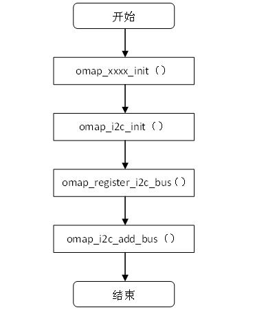
图3.1 Platform device注册过程
函数omap_i2c_add_bus()中,通过函数platform_device_register()注册Platform device到platform bus上,代码如下:
static int __init omap_i2c_add_bus(int bus_id)
{
	struct platform_device *pdev;
	struct resource *res;
	resource_size_t base, irq;
    ……
	……
	return platform_device_register(pdev);
}
注册完成后,中断号及寄存器的基地址等信息会在设备树中描述了,此后只需利用platform_get_resource等标准接口自动获取即可,实现了驱动和资源的分离。
3.2 I2C adapter的Platform driver
Andrord 2.1中Platform driver的注册的代码位于内核的drivers/i2c/busses/ i2c-omap.c中,该驱动的注册目的是初始化OMAP3630的I2C adapter,提供I2C总线传输的具体实现,并且向I2C core注册I2C adapter。
3.2.1 Platform driver的定义
在文件drivers/i2c/busses/ i2c-omap.c中,platform driver定义如下:
static struct platform_driver omap_i2c_driver = {
	.probe		= omap_i2c_probe,
	.remove		= omap_i2c_remove,
	.driver		= {
		.name	= "i2c_omap",
		.owner	= THIS_MODULE,
	},
};
3.2.2 Platform driver的注册
在文件drivers/i2c/busses/ i2c-omap.c中,platform driver注册如下:
/* I2C may be needed to bring up other drivers */
static int __init
omap_i2c_init_driver(void)
{
	return platform_driver_register(&omap_i2c_driver);
}
subsys_initcall(omap_i2c_init_driver);
通过platform_driver_register()函数注册Platform driver omap_i2c_driver时,会扫描platform bus上的所有设备,由于匹配因子是name即"i2c_omap",而之前已经将name为"i2c_omap"的Platform device注册到platform bus上,因此匹配成功,调用函数omap_i2c_probe将设备和驱动绑定起来。
在drivers/i2c/busses/ i2c-omap.c中会涉及到一个数据结构omap_i2c_dev,这个结构定义了omap3630的I2C控制器,结构如下:
struct omap_i2c_dev {
	struct device		*dev;
	void __iomem		*base;		/* virtual */
	int			irq;
	struct clk		*iclk;		/* Interface clock */
	struct clk		*fclk;		/* Functional clock */
	struct completion	cmd_complete;
	struct resource		*ioarea;
	u32			speed;		/* Speed of bus in Khz */
	u16			cmd_err;
	u8			*buf;
	size_t			buf_len;
	struct i2c_adapter	adapter;
	u8			fifo_size;	/* use as flag and value
						 * fifo_size==0 implies no fifo
						 * if set, should be trsh+1
						 */
	u8			rev;
	unsigned		b_hw:1;		/* bad h/w fixes */
	unsigned		idle:1;
	u16			iestate;	/* Saved interrupt register */
	u16			pscstate;
	u16			scllstate;
	u16			sclhstate;
	u16			bufstate;
	u16			syscstate;
	u16			westate;
};
Base对应I2C控制器寄存器的虚拟地址。
Irq对应I2C控制器的中断号。
Buf对应上层传下来的需要发送数据或者I2C控制接收到数据的缓存空间,buf_len是其大小。
Adapter对应I2C控制器的适配器结构。
U16类型的各个state变量是用于对应I2C控制器的寄存器的值。
函数omap_i2c_probe的执行流程如下图:
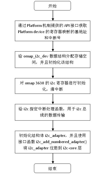
图3.2 omap_i2c_probe的执行流程
函数omap_i2c_probe的简要代码如下:
static int __init
omap_i2c_probe(struct platform_device *pdev)
{
	struct omap_i2c_dev	*dev;
	struct i2c_adapter	*adap;
	struct resource		*mem, *irq, *ioarea;
	irq_handler_t isr;
	……

	/* NOTE: driver uses the static register mapping */
	mem = platform_get_resource(pdev, IORESOURCE_MEM, 0);
	……
	irq = platform_get_resource(pdev, IORESOURCE_IRQ, 0);
	……
	dev = kzalloc(sizeof(struct omap_i2c_dev), GFP_KERNEL);
	……
	dev->dev = &pdev->dev;
	dev->irq = irq->start;
	dev->base = ioremap(mem->start, mem->end - mem->start + 1);
	……
	/* reset ASAP, clearing any IRQs */
	omap_i2c_init(dev);

	isr = (dev->rev < OMAP_I2C_REV_2) ? omap_i2c_rev1_isr : omap_i2c_isr;
	r = request_irq(dev->irq, isr, 0, pdev->name, dev);
	……
	adap = &dev->adapter;
	i2c_set_adapdata(adap, dev);
	adap->owner = THIS_MODULE;
	adap->class = I2C_CLASS_HWMON;
	strncpy(adap->name, "OMAP I2C adapter", sizeof(adap->name));
	adap->algo = &omap_i2c_algo;
	adap->dev.parent = &pdev->dev;
	/* i2c device drivers may be active on return from add_adapter() */
	adap->nr = pdev->id;
	r = i2c_add_numbered_adapter(adap);
	……
	return 0;
    ……
}
这里定义了I2C adapter的中断处理函数omap_i2c_isr(),该函数对I2C控制器的中断事件进行响应,主要实现了对I2C数据收发中断事件的处理。
这边还涉及到了一个i2c_algorithm结构的变量omap_i2c_algo,该变量的定义如下:
static const struct i2c_algorithm omap_i2c_algo = {
	.master_xfer	= omap_i2c_xfer,
	.functionality	= omap_i2c_func,
};
omap_i2c_xfer接口函数实现了底层I2C数据传输的方法。
omap_i2c_probe函数最后使用了 i2c_add_numbered_adapter()将adapter注册到i2c-core层,adapter的总线号保存在平台设备数组 omap_i2c_devices中,见3.1.1节,由于该数组中有三个成员,即三条I2C总线,所以这里会建立三个I2C adapter,总线号分别为1,2,3。