1.5 Constraints and Assumptions 1
2 High-Level POC Architecture 3
3.1 Sequence Diagram for Iaas & SaaS 4
4.1 Server Physical Infrastructure 6
Server Physical Machine Table 6
6 Configure Exchange Server 2010 17
6.2 Configuring Hosted Exchange using PowerShell 23
7 TroubleShooting refrences 35
7.2 Troubleshooting Exchange Setup 35
Appendix A – Hyper-V Host Server Farm Pattern 36
Appendix B – Host Cluster patterns 37
Node and File Share Majority 37
Appendix C – Network Architecture 39
Appendix D - Processor Architecture 40
Appendix E – Memory Architecture 41
Appendix G - Disk Redundancy Architecture 43
Appendix H - Fibre Channel Storage Area Network 44
Appendix I - Disk Controller or HBA Interface 45
Appendix J - Cluster Shared Volumes 46
Appendix K - System Center Virtual Machine Manager R2 2008 48
Virtual Machine Manager Server 48
Microsoft SQL Server Database 48
Delegated Management and Provisioning Web Portal 49
Appendix L – Hyper-V Overview 50
Appendix M – Hardware Architecture 51
Cluster Host Server Overview 53
-
Introduction
The Private Cloud-POC is a self-contained virtualised management infrastructure which can be deployed in a suitable environment to show the use of Microsoft Technologies in provisioning and managing Virtual Machines. This document covers the deployment details to allow the technical personnel involved in deployment the solution to understand what components are involved and how they are configured.
The Private Cloud-POC User Guide provides the information you need deploy and Configure the Virtual Machine Manager Self-Service Portal (VMMSSP, or the self-service portal) in your datacenter and Exchange Server.
-
About this Document
This document is for Private Cloud and provides a deployment scenario for self-service portal component guide and Exchange Server Mailbox.
-
Intended Audience
The intended audience of this document is the technical personnel engaged in implementing the Virtual Machine Manager Self-Service Portal and Exchange Services solution within their own environment.
-
Document Scope
The scope of this document is concerned with Microsoft technologies only.
-
Constraints and Assumptions
The server and storage hardware required for the GPC-POC
environment is as specified by the hosting partner provided it meets the minimum requirements as defined in this document.
There are also a lot of related conditions and technologies that will have an impact on the GPC-POC working. Some of those assumptions are listed in the table below:
|
Assumptions |
Explanation |
|
Physical environment |
It is assumed that a server environment exists with enough floor space, power, air conditioning, physical security etc. |
|
Stable network |
It is assumed that the local and wide area network infrastructure which includes physical components switches, routers, cable etc. And the logical components like routing, broadcasts, collisions etc. Are stable and under control. Having an unstable network can result in unexpected behavior. |
|
Namespace |
Maintain Isolated / Unique Namespace |
|
Network Support |
Failover / Router / Configuration needs to be performed by IT staff. |
|
Constraints |
Explanation |
|
DHCP Required |
DHCP is required for VM Provisioning |
|
Network Bandwidth |
1 GB network bandwidth |
|
Multiple VLANS / NICS |
Multiple VLANS / NICS required for Clustering, Live Migration and Heartbeat |
|
iSCSI Hardware |
Required 500 GB – 1 TB on iSCSI |
Table 1: Constraints and Assumptions
-
Known Issues
-
No limitations on the number of VMs that a user can request. Potential future enhancement.
-
Cannot remote control a Linux machine currently (as there is no RDP connectivity). Potential to implement a telnet/X-Windows session instead in the future.
-
No automatic SCOM agent install for provisioned Linux machines. Potential future enhancement to include the agent in the source.
All Virtual machines are provisioned on same network and as such users can see all other machines on the network (but do not have logon access). Potential future enhancement to build VMs into separate VLANs but needs consideration of management infrastructure.
-
High-Level POC Architecture

Figure 0.1: High Level POC Architecture
-
POC is intended to be delivered on harddrive for installation at customer site with limited hardware investment.
-
It's only require 6-8 physical machines
-
Goal is to demonstrate IaaS & SaaS scenarios for Private Cloud deployment environment.
-
The POC uses a Windows iSCSI server instead of a SAN for portability reasons. iSCSI is a storage protocol used to connect to a network device that moves storage-related data. It allows clients to send SCSI commands to remote, consolidated storage targets (or disk arrays) in the same way the client can interact with a locally attached disk. A common misconception is that you can connect iSCSI over your existing LAN infrastructure.
-
High-Level Scenarios
|
High-Level Showcase Scenarios (10-15) |
|
|
IaaS (Dynamic Datacenter) |
SaaS (Exchange) |
|
1. New tenant (organization) sign-up |
1. New tenant (organization) sign-up |
|
2. New environment provisioning request |
2. New tenant services configuration |
|
3. Virtual machine request |
3. Tenant admin set-up |
|
4. Virtual machine template setting |
4. New user (mailbox) addition |
|
5. Virtual machine provisioning |
5. Distribution list management rights assignment |
|
6. Reporting |
6. Charge back reporting |
-
Sequence Diagram for Iaas & SaaS

Figure 0.2: Sequence Diagram for Iaas & SaaS
Following are the sequence diagram steps
-
Business Group Customer requested for Emailbox setup for the department / organization.
-
Request goes to IT Aministrator of the department / organization. IT Admin enters the New Machine request through Website Form.
-
It goes to Data Center Admin approval for VMs aqquision. Once approved, approval mail sent to IT Adminstrator.
-
IT Administrator request for the VM Servers.
-
IT Administrator configure and installs the Exchange on VM Servers.
-
IT Administrator Provision and Add Tenant and Mailbox for users.
-
Finally the request gets completed and mail been send to BG Customer to utilize the services.
-
Report gets generated based on the service(space, bandwidth, etc..) usage and charge back to the department based on the usage.
-
Solution Design
-
The GPC-POC is based on a self-contained domain environment consisting of a number of management servers to support a scalable Hyper-V cluster onto which the solution will provision multiple Virtual Machines:
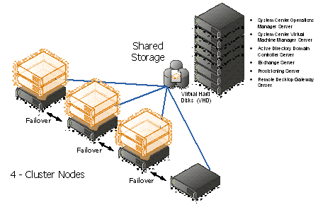
Figure 3: Hyper-V cluster Nodes with Virtual Machine
In order to make the solution as portable as possible, the management servers are themselves provided as virtual machines. This allows them to be scaled at the virtual host level to higher levels of memory/processor and disk as required without losing any portability.
The actual GPC-POC components in the handover consist only of the virtual machines making up the management servers. The associated Hyper-V Cluster needs to be created after the management servers are in place in the environment as it will need to be joined to the GPC-POC domain.
Providing a Hyper-V Cluster as the Virtualisation platform allows for fast transfer of the virtual machine servers to a different physical server in the event of unexpected hardware failure of the host. Live Migration will be used in the event of scheduled maintenance on the host servers and will provide continuous service with no outage or service loss.
The sections below covers the detailed configuration for the GPC-POC Infrastructure Environment.
-
Server Physical Infrastructure
Server Physical Machine Table
|
Base OS Server Name |
Assigned Machine |
Bits |
RAM |
CPU |
Disks |
Virtual Switch "Public" |
Virtual Switch "Hyper-V & Exchange Replication" |
Purpose |
|
HPB1 (HPV1) |
HP Blade 1 |
x64 |
64 GB |
Quad Core |
2 X 150 GB (300 GB) |
Gigabit Ethernet External NIC1 10.1.1.x VLAN1 Corp or VPN |
Gigabit Ethernet External NIC2 10.1.2.x VLAN2 Lab internal |
Hyper-V (cluster) DDC (SQL, DIT-SC, SCCM, SCOM, SCVMM + Library) Exchange CAS + Hub |
|
HPB2 (HPV2) |
HP Blade 2 |
x64 |
64 GB |
Quad Core |
2 X 150 GB (300 GB) |
Gigabit Ethernet External NIC1 10.1.1.x VLAN1 Corp or VPN |
Gigabit Ethernet External NIC2 10.1.2.x VLAN2 Lab internal |
Hyper-V failover for HPV1 |
|
HPB3 (HPV3) |
HP Blade 3 |
x64 |
32 GB |
Quad Core |
2 X 150 GB (300 GB) |
Gigabit Ethernet External NIC1 10.1.1.x VLAN1 Corp or VPN |
Gigabit Ethernet External NIC2 10.1.2.x VLAN2 Lab internal |
Hyper-V (cluster) DAS (273GB - RAID5) Exchange DAG |
|
HPB4 (HPV4) |
HP Blade 4 |
x64 |
32 GB |
Quad Core |
2 X 150 GB (300 GB) |
Gigabit Ethernet External NIC1 10.1.1.x VLAN1 Corp or VPN |
Gigabit Ethernet External NIC2 10.1.2.x VLAN2 Lab internal |
Hyper-V (cluster) DAS (273GB - RAID5) Exchange DAG |
|
IBMH1 |
IBM 3850 + 2 Fusion IO cards |
x64 |
16 GB |
Quad Core Intel Xeon Series 7400 |
2 X 650 GB Fusion IO |
Gigabit Ethernet External NIC1 10.1.1.x VLAN1 Corp or VPN |
N/A |
Hyper-V Dual NIC gateway host for remote access AD+DNS until Lenovo server is made available |
|
IBMH2 |
IBM 3850 |
x64 |
12 GB |
Quad Core Intel Xeon Series 7400 |
|
Gigabit Ethernet External NIC1 10.1.1.x VLAN1 Corp or VPN |
N/A |
iSCSI |
|
LENH1 |
Lenovo RD210 |
x64 |
8 GB |
|
|
Gigabit Ethernet External NIC1 10.1.1.x VLAN1 Corp or VPN |
N/A |
Server missing hard drive and won't be available before week of June 21. AD+DNS |
Table 2: Server Physical Machine Table
For more details on the lab configuration, please refer the Excel sheet attached in the Appendix N
-
SCVMM Web Portal
This section will show you how to use the SCVMM Web Portal, please find the screen shots in the sequence, which is self-explanatory.
Login to the SCVMM Web Portal as per the screen below. Enter the Admin User id and paword.

Figure 1: Access SCVMM Web Portal
Click on Register New Business Unit
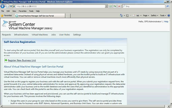
Figure 2: SCVMM Web Portal – Self Service Registration
Please enter all the required field as shown below in the screen.

Figure 3: SCVMM Web Portal – Self Service Registration
Click on "Submit" button

Figure 4: SCVMM Web Portal – Self Service Registration
As you can see the request has been submitted for the approval.
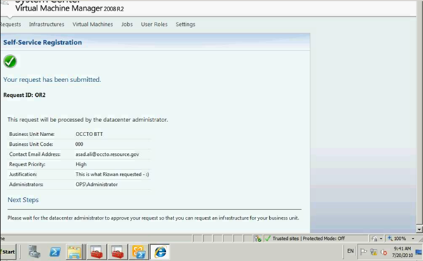
Figure 5: SCVMM Web Portal – Self Service Request Submission
Administrator can see the submission of the request to Approve or Reject.
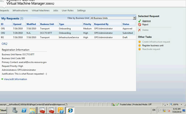
Figure 6: SCVMM Web Portal – Self Service Request Submission
Please enter the Approval / Reject comments.
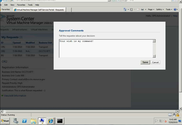
Figure 7: SCVMM Web Portal – Self Service Request Submission
Click on "Create infrastrure request"

Figure 8: SCVMM Web Portal – Self Service Request Approval
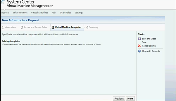
Enter the required fields as shown below
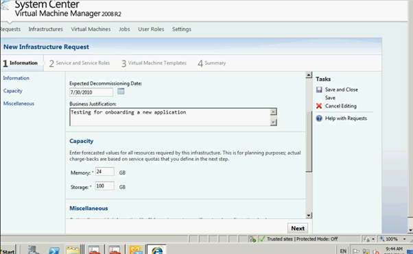
Figure 9: SCVMM Web Portal – Infrasturcture Request
Once completed click on Next button and it will go to Service Setup page

Figure 10: SCVMM Web Portal – Infrasturcture Request
Enter all the info as per the screen below.

Figure 11: SCVMM Web Portal –Service Setup page
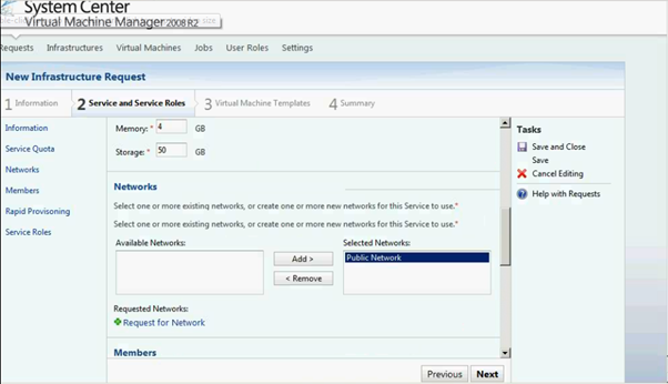
Figure 12: SCVMM Web Portal –Service Setup page
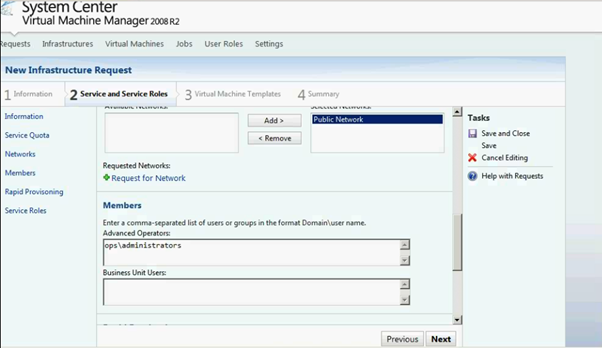
Figure 13: SCVMM Web Portal –Service Setup page
Click on Add Service Role link
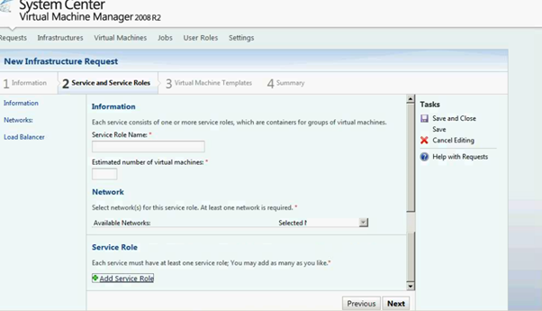
Figure 14: SCVMM Web Portal –Service Setup page
Enter the Service Role info on the below screen

Figure 15: SCVMM Web Portal –Service Role Setup page
Click on next and it will return to Service setup page.
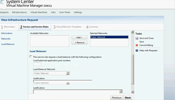
Figure 16: SCVMM Web Portal –Service Role Setup page
As you can see the screen below Service role has been added. You can delete / edit as it's required.

Figure 17: SCVMM Web Portal –Service Setup page

Figure 18: SCVMM Web Portal –Service Setup page