从这篇文章开始,开始学习MPLS VPN的学习。
先讲讲VPN(virtual private network),即虚拟专有网络。如果用OSI的七层概念来说的话,第一层的专有网络是最容易直接,但也可以说是最不容易最不直接的一种方式,两个远程站点之间拉一条专线,这就可以组一条专网。很简单吧,但是也可以说是很麻烦。比方说这两个站点,一个在北京一个在纽约,那么这条专线还要跨越大海洋呢!当然我们也可以租用运营商已经铺好的线路,但是这个费用是相当昂队的。
第二层的VPN就有好多了。比方说老一点的技术:X.25,Frame-relay,ATM。X.25在以前用的很多,但是因为其带宽比较低现在已经淘汰了。FR倒是还有在用,暑假的时候中兴银行的网络改造时,用的就是FR连接各个分部。他们都是第二层的技术,FR使用DLCI进行路由,首先建立了一条虚拟的链路,然后在这条链路上跑路由和数据。ATM也是类似的方式,只不过使用的是PVI/PCI。对于运营商来说,客户的路由信息都是不可见的。这种VPN的缺点就是拓展性比较差,对QoS支持有限。
第三层的VPN一般都是后期的技术了,如GRE,IPSec。他们在第三层上建立一条链路,然后在这条链路上跑用户的路由和数据。对运营商来说,客户的路由信息也是不可见的。这种VPN的缺点也有拓展性的问题。不过IPSce现在用的依然很多,他提供了非常好的安全性能,在远程访问方面优势明显,我个人感觉他相对与第二层VPN的一个重要不同就是他没有对运营商提出什么要求,用户可以在运营商提供的常规路由基础上完成IPSec的铺设,不过他一般需要特别的硬件支持和软件支持。(当然路由器和防火墙也可以实现硬件VPN)。在CCIE安全方向还有比较深入的考察,正在学习中。
相关的书籍上也常用另一种方式来分类VPN,即覆盖型的VPN和对等体型的VPN。区别这两种类型的VPN的关键点就是运营商是否了解客户的路由信息。MPLS VPN就是一种对等模型的VPN,运营商边界路由器获取客户端的路由信息,然后在传输给对端的客户,建立一种端到端的模型,很好的解决了覆盖型VPN的局限。
一些基本的概念。
VRF :VPN路由与转发表,对应的VPN的路由表,PE通过VRF隔离不同VPN客户的路由。我们也可以这么理解,PE路由器内部虚拟出了多个路由器,虚拟路由器的路由表就是VRF。
RD:路由区分符,他用于区分每一条路由,不同VPN客户之间如果不同信的话就运行重叠的IP编制,实现的方法就是通过RD来区分。这是一个64字节字段,在MPLS VPN中与IP地址组合成VPNv4地址。
RT:路由目标,决定VRF的导入与导出。
下面的这个实验实在纯粹的IP上来建立虚拟路由表实现路由,没有使用MPLS,这样可以比较直观的认识VRF。
拓扑:
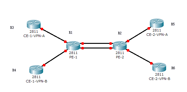
说明:
1. R3,R5是公司A的两个远程分部,R4,R6是公司B的两个远程分部,R1,R2为运营商的骨干网路由器。
2. 骨干网络内部使用OSPF建立互联,PE-CE间使用OSPF建立互联。
3. R5,R6使用重叠的地址区间192.168.100.0/24
4. 实验设备间的互联使用子接口定义vlan id来区分不同的链路。
5. R1:PE1; R2:PE2; R3:CE1-VPN-A; R4:CE2-VPN-A R5:CE2-VPN-A; R6 :CE2-VPN-B
1. 基础配置,完成IP分配。
R1#sh ip int brie
Interface IP-Address OK? Method Status Protocol
FastEthernet0/0 unassigned YES manual up up
FastEthernet0/0.12 12.1.1.1 YES manual up up
FastEthernet0/0.13 13.1.1.1 YES manual up up
FastEthernet0/0.14 14.1.1.1 YES manual up up
FastEthernet0/0.21 21.1.1.1 YES manual up up
R2#sh ip int brie
Interface IP-Address OK? Method Status Protocol
FastEthernet0/0 unassigned YES manual up up
FastEthernet0/0.12 12.1.1.2 YES manual up up
FastEthernet0/0.21 21.1.1.2 YES manual up up
FastEthernet0/0.25 25.1.1.2 YES manual up up
FastEthernet0/0.26 26.1.1.2 YES manual up up
R3#sh ip int brie
Interface IP-Address OK? Method Status Protocol
FastEthernet0/0 unassigned YES manual up up
FastEthernet0/0.13 13.1.1.3 YES manual up up
Loopback0 3.3.3.3 YES manual up up
R4#sh ip int brie
Interface IP-Address OK? Method Status Protocol
FastEthernet0/0 unassigned YES manual up up
FastEthernet0/0.14 14.1.1.4 YES manual up up
Loopback0 4.4.4.4 YES manual up up
R5#sh ip int brie
Interface IP-Address OK? Method Status Protocol
FastEthernet0/0 unassigned YES manual up up
FastEthernet0/0.25 25.1.1.5 YES manual up up
Loopback0 192.168.100.1 YES manual up up
R6#sh ip int brie
Interface IP-Address OK? Method Status Protocol
FastEthernet0/0 unassigned YES manual up up
FastEthernet0/0.26 26.1.1.6 YES manual up up
Loopback0 192.168.100.1 YES manual up up
*R5,R6使用loopback接口模拟内部网络,掩码为/24,使用ip ospf network point-to-point去主机路由。
2. 建立VRF。
VRF对于客户路由器来说是透明的,只需在运营商网络内部的PE路由器上建立即可。对于本拓扑来说就是在R1,R2。因为这里有两个客户网络需要建立VPN,所以要建立两个VRF。
下面这段代码在R1,R2上是完全一样的。当然也可以不一样。关于RD,RT的设置问题曾经也迷惑了我一段时间,这个问题以后可以专门的来讨论一下,这里先略过不说。
ip vrf VPN-A
rd 1:100
route-target export 1:100
route-target import 1:100
!
ip vrf VPN-B
rd 1:200
route-target export 1:200
route-target import 1:200
3. 在接口下启用VRF
VRF路由表建立完成以后就需要在相应的接口下启用。在MPLS VPN中我们在PE-CE的接口上启用,但是本实验因为没有启用MPLS,纯粹依靠VRF来实现路由,因此需要建立一跳完成的VRF路径,也就是说,我们也要在运营商的骨干网内部路由器间的接口上启用VRF。
R1(PE1)
!
interface FastEthernet0/0.12
description **--->PE2:VPN-A**
encapsulation dot1Q 12
ip vrf forwarding VPN-A
ip address 12.1.1.1 255.255.255.0
!
interface FastEthernet0/0.13
description **--->CE1:VPN-A**
encapsulation dot1Q 13
ip vrf forwarding VPN-A
ip address 13.1.1.1 255.255.255.0
!
interface FastEthernet0/0.14
description **--->CE2:VPN-B**
encapsulation dot1Q 14
ip vrf forwarding VPN-B
ip address 14.1.1.1 255.255.255.0
!
interface FastEthernet0/0.21
description **--->PE2:VPN-B**
encapsulation dot1Q 21
ip vrf forwarding VPN-B
ip address 21.1.1.1 255.255.255.0
!
R2:
!
interface FastEthernet0/0.12
description **--->PE1:VPN-A**
encapsulation dot1Q 12
ip vrf forwarding VPN-A
ip address 12.1.1.2 255.255.255.0
!
interface FastEthernet0/0.21
description **--->PE1:VPN-B**
encapsulation dot1Q 21
ip vrf forwarding VPN-B
ip address 21.1.1.2 255.255.255.0
!
interface FastEthernet0/0.25
description **--->CE2:VPN-A**
encapsulation dot1Q 25
ip vrf forwarding VPN-A
ip address 25.1.1.2 255.255.255.0
!
interface FastEthernet0/0.26
description **--->CE2:VPN-B**
encapsulation dot1Q 26
ip vrf forwarding VPN-B
ip address 26.1.1.2 255.255.255.0
!
*前面我们在基础配置中配置了IP地址,当我们在接口下启用了相应的VRF后这些地址都会丢失,这种丢失的正常的。VRF相当与在本地路由器上又虚拟了出了一个路由器,这个路由器的IP路由表就是VRF。因此,我们原先配置的IP地址是处于本地的IP路由表里面的,当我们把这个接口从本地路由器迁移到虚拟路由器里时,这个常规IP路由表里面的IP地址自然就失效了。然后我们再配置一个相同的IP地址时,这个地址就是在对应的虚拟路由表里面了。如下所示:
R2(config)#in fa0/0.25
R2(config-subif)#ip vrf for VPN-A
% Interface FastEthernet0/0.25 IP address 25.1.1.2 removed due to enabling VRF VPN-A
R2(config-subif)#ip add 25.1.1.2 255.255.255.0
R2#sh ip route vrf VPN-A connected
25.0.0.0/24 is subnetted, 1 subnets
C 25.1.1.0 is directly connected, FastEthernet0/0.25
12.0.0.0/24 is subnetted, 1 subnets
C 12.1.1.0 is directly connected, FastEthernet0/0.12
因此,我们也可以先不配置常规的IP地址,等在对应的接口下启用了VRF后再配上IP地址。本实验之所以先配上是因为启用了大量的虚拟子接口,先配上IP后用ping检测下接口间的配置是否都正确。
4. 启用OSPF建立VRF路由
建立VRF路由的方法有多种,如route-static,OSPF,EIGRP,ISIS,RIP,BGP,与常规的路由基本一致。关键的一点就是加上vrf xx参数。
本实验使用OSPF建立。之后也会给出用其他动态路由协议建立的一些说明。
因为VRF路由表是在PE上建立的,所以,只有PE路由器上需要建立相应的路由协议,CE设备正常启用OSPF即可。
R1#sh run | b router ospf
router ospf 35 vrf VPN-A
router-id 12.1.1.1
log-adjacency-changes
network 12.1.1.1 0.0.0.0 area 0
network 13.1.1.1 0.0.0.0 area 1
!
router ospf 46 vrf VPN-B
log-adjacency-changes
network 14.1.1.1 0.0.0.0 area 1
network 21.1.1.1 0.0.0.0 area 0
R2#sh run | b router ospf
router ospf 35 vrf VPN-A
router-id 2.2.2.2
log-adjacency-changes
network 12.1.1.2 0.0.0.0 area 0
network 25.1.1.2 0.0.0.0 area 2
!
router ospf 46 vrf VPN-B
router-id 21.1.1.2
log-adjacency-changes
network 21.1.1.2 0.0.0.0 area 0
network 26.1.1.2 0.0.0.0 area 2
R3#sh run | b router ospf
router ospf 35
router-id 3.3.3.3
log-adjacency-changes
network 3.3.3.3 0.0.0.0 area 1
network 13.1.1.3 0.0.0.0 area 1
R4#sh run | b router ospf
router ospf 46
router-id 4.4.4.4
log-adjacency-changes
network 4.4.4.4 0.0.0.0 area 1
network 14.1.1.4 0.0.0.0 area 1
R5#sh run | b router ospf
router ospf 35
router-id 5.5.5.5
log-adjacency-changes
network 25.1.1.5 0.0.0.0 area 2
network 192.168.100.0 0.0.0.255 area 2
R6#sh run | b router ospf
router ospf 46
router-id 6.6.6.6
log-adjacency-changes
network 26.1.1.6 0.0.0.0 area 2
network 192.168.100.0 0.0.0.255 area 2
5. 检查验收
R3#sh ip route ospf
25.0.0.0/24 is subnetted, 1 subnets
O IA 25.1.1.0 [110/30] via 13.1.1.1, 00:41:03, FastEthernet0/0.13
12.0.0.0/24 is subnetted, 1 subnets
O IA 12.1.1.0 [110/20] via 13.1.1.1, 00:41:03, FastEthernet0/0.13
O IA 192.168.100.0/24 [110/31] via 13.1.1.1, 00:41:03, FastEthernet0/0.13
如上所示,R3已经收到了192.168.100.0/24的路由。
R3#ping 192.168.100.1 sour l0
Type escape sequence to abort.
Sending 5, 100-byte ICMP Echos to 192.168.100.1, timeout is 2 seconds:
Packet sent with a source address of 3.3.3.3
!!!!!
Success rate is 100 percent (5/5), round-trip min/avg/max = 44/59/68 ms
也能够ping通。
如拓扑说明部分所述,R5,R6使用了重叠的地址空间,那么,这个到达的192.168.100.1我们预期是到达R5上的,我们通过debug来验证。
R5(config)#acce 100 per icmp host 3.3.3.3 host 192.168.100.1 echo
R5(config)#do debug ip pack 100
IP packet debugging is on
R6(config)#acce 100 per icmp host 3.3.3.3 host 192.168.100.1 echo
R6(config)#do debug ip pack 100
IP packet debugging is on
回到R3发送一个ping到达192.168.100.1的ping包,然后去R5,R6上看debug输出。
R5#
*Mar 1 01:27:51.835: IP: tableid=0, s=3.3.3.3 (FastEthernet0/0.25), d=192.168.100.1 (Loopback0), routed via RIB
*Mar 1 01:27:51.839: IP: s=3.3.3.3 (FastEthernet0/0.25), d=192.168.100.1, len 100, rcvd 4
从R5的debug输出中我们就可以看出数据包的源是R3了。
R6输出为空。
这样就说明了R3,R5间建立了端到端的VPN了。其实直接去R5,R6上看看有没有R3的路由就能知道R3ping通的是谁了!
R5#sh ip route ospf
3.0.0.0/32 is subnetted, 1 subnets
O IA 3.3.3.3 [110/31] via 25.1.1.2, 00:49:41, FastEthernet0/0.25
12.0.0.0/24 is subnetted, 1 subnets
O IA 12.1.1.0 [110/20] via 25.1.1.2, 00:52:27, FastEthernet0/0.25
13.0.0.0/24 is subnetted, 1 subnets
O IA 13.1.1.0 [110/30] via 25.1.1.2, 00:52:27, FastEthernet0/0.25
R6#sh ip route ospf
4.0.0.0/32 is subnetted, 1 subnets
O IA 4.4.4.4 [110/31] via 26.1.1.2, 00:51:51, FastEthernet0/0.26
21.0.0.0/24 is subnetted, 1 subnets
O IA 21.1.1.0 [110/20] via 26.1.1.2, 00:52:33, FastEthernet0/0.26
14.0.0.0/24 is subnetted, 1 subnets
O IA 14.1.1.0 [110/30] via 26.1.1.2, 00:52:33, FastEthernet0/0.26
也就是说,如果在R4上ping 192.168.100.1的话,那么这个数据包是被路由到R6的。
R4#ping 192.168.100.1 sour l0
Type escape sequence to abort.
Sending 5, 100-byte ICMP Echos to 192.168.100.1, timeout is 2 seconds:
Packet sent with a source address of 4.4.4.4
!!!!!
Success rate is 100 percent (5/5), round-trip min/avg/max = 56/72/88 ms
下面是R1上的路由表,他能够更直观的反映出VPN对于隔离用户路由的作用。
R1#sh ip route vrf VPN-A
(…omitted)
Routing Table: VPN-A
Gateway of last resort is not set
3.0.0.0/32 is subnetted, 1 subnets
O 3.3.3.3 [110/11] via 13.1.1.3, 00:52:15, FastEthernet0/0.13
25.0.0.0/24 is subnetted, 1 subnets
O IA 25.1.1.0 [110/20] via 12.1.1.2, 00:52:15, FastEthernet0/0.12
12.0.0.0/24 is subnetted, 1 subnets
C 12.1.1.0 is directly connected, FastEthernet0/0.12
13.0.0.0/24 is subnetted, 1 subnets
C 13.1.1.0 is directly connected, FastEthernet0/0.13
O IA 192.168.100.0/24 [110/21] via 12.1.1.2, 00:52:15, FastEthernet0/0.12
R1#sh ip route vrf VPN-B
(…omitted)
Gateway of last resort is not set
4.0.0.0/32 is subnetted, 1 subnets
O 4.4.4.4 [110/11] via 14.1.1.4, 00:54:11, FastEthernet0/0.14
21.0.0.0/24 is subnetted, 1 subnets
C 21.1.1.0 is directly connected, FastEthernet0/0.21
26.0.0.0/24 is subnetted, 1 subnets
O IA 26.1.1.0 [110/20] via 21.1.1.2, 00:54:11, FastEthernet0/0.21
14.0.0.0/24 is subnetted, 1 subnets
C 14.1.1.0 is directly connected, FastEthernet0/0.14
O IA 192.168.100.0/24 [110/21] via 21.1.1.2, 00:54:11, FastEthernet0/0.21
好这个实验到这里基本就结束了。
前面我们我们说PE-CE间启用IGP的话可以有多种路由协议。其实,OSPF不是最好的方法,这是他自身的原因导致的。RIP,EIGRP,ISIS都可以在一个路由进程下通过地址族来实现多个VRF,但是OSPF却只能启用多个路由进程。在本实验中只有两个VPN,如果PE有20个甚至更多的VPN客户时,使用OSPF将带来巨大的开销,不光是管理开销,更严重的是路由器的CPU和内存占用。
下面的配置事例是在PE上如何使用RIP,EIGRP和ISIS来建立PE-CE间的路由。
router rip
version 2
no auto-summary
!
address-family ipv4 vrf VPN-B
network 14.0.0.0
network 21.0.0.0
no auto-summary
version 2
exit-address-family
!
address-family ipv4 vrf VPN-A
network 12.0.0.0
network 13.0.0.0
no auto-summary
version 2
exit-address-family
!
router eigrp 10
no auto-summary
!
address-family ipv4 vrf VPN-B
network 14.1.1.1 0.0.0.0
network 21.1.1.1 0.0.0.0
no auto-summary
autonomous-system 46
exit-address-family
!
address-family ipv4 vrf VPN-A
network 12.1.1.1 0.0.0.0
network 13.1.1.1 0.0.0.0
no auto-summary
autonomous-system 35
exit-address-family
!
RIP和EIGRP总是能看到许多相同之处,这里我们又领略了一次。最后一个ISIS配置就很简单了,本来在ISIS中发布一个网段即使直接在接口下使用ip router isis,因此配置VRF基本与以前的配置方法一样,不同就是在接口下就加上一个ip vrf for XX来实现关联。
在IPv6中的配置方法也吸取了ISIS的配置方法,直接在接口下启用。其实在新版本的IOS中我们也可以在在接口下直接将宣告,但是只限于OSPF,其他的路由协议还没有支持。
好,到此结束。RD,RT的设置问题以后再讨论吧。
本文出自 “海阔天空” 博客,请务必保留此出处http://edges.blog.51cto.com/705035/401063